Postingan

Menampilkan postingan dari 2015

Dot Matrix 8x8

Gambar
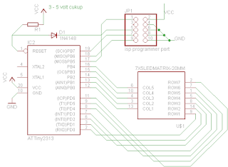
above that pic, we can identifiy which one the coloums and rows (a,b,d,c,e,f,g,dotpoint) portD (atmega8) most scheme connected as rows meanwhile portB (in arduino call D8 .. D13) connected as coloums. need more 2 wire for coloums try use portC and the question is how the code ?

LOVE HURT Scheme circuit Electronic skema rangkaian elektronika

Gambar

LOVE HURT coding

#define F_CPU 1000000UL #include #include #include #include #include //Progmem simpannya di FLASH memory const char love1[] PROGMEM = { 0b0011110, 0b0100001, 0b1000010, 0b0100001, 0b0011110 }; const char love2[] PROGMEM = { 0b0001100, 0b0010010, 0b0100100, 0b0010010, 0b0001100 }; const char L[] PROGMEM ={0x7f, 0x7f, 0x40, 0x40, 0x20}; const char O[] PROGMEM ={0x3e, 0x7f, 0x41, 0x41, 0x3e}; const char V[] PROGMEM ={0x3f, 0x7e, 0x40, 0x20, 0x1f}; const char E[] PROGMEM ={0x7f, 0x7f, 0x49, 0x49, 0x41}; const char H[] PROGMEM ={0x7f, 0x7f, 0x08, 0x08, 0x7f}; const char U[] PROGMEM ={0x3f, 0x7f, 0x40, 0x40, 0x3f}; const char R[] PROGMEM ={0x7f, 0x7f, 0x11, 0x29, 0x46}; const char T[] PROGMEM ={0x03, 0x03, 0x7f, 0x03, 0x02}; const char creature[]={0x4e, 0x31, 0x35, 0x31, 0x4e}; //simpan di memory/RAM aja uint8_t EEMEM tengkorak[5]= {0x1e, 0x75, 0x61, 0x75, 0x1e}; //simpan di EEPROM uint8_t EEMEM pacman[5]= {0x26, 0x67, 0x67, 0x7f, 0x3e}; //simpan di EEPROM char dotnya[5],s

TUJUHBELAS PROYEK BELAJAR ARDUINO

Review buku TUJUHBELAS PROYEK BELAJAR ARDUINO Pengarang Ir Ilmanza R.K. penerbit robomania.tokobagus.com download : http://dokumen.tips/documents/17-proyek-arduino-r2.html berisi contoh skema dan program untuk arduino board. Blinking LED Traffic Light Switch on off Potensio meter Alarm Ring tone output PWM Display LCD Sensor Cahaya Termometer digital pengukur jarak pendeteksi gerak Remote control 31 14. SENSOR GARIS / DETEKTOR WARNA . . . . . . . . . . . . . . . . . . . . . . . . . . . . . . . . . . 33 15. SWITCH ON/OFF PERALATAN LISTRIK DENGAN RELAY . . . . . . . . . . . . . . . . . . . 35 16. MENGGERAKKAN LENGAN ROBOT DENGAN SERVO . . . . . . . . . . . . . . . . . . . . . . 36 17. H-BRIDGE MOTOR DRIVER . baca juga http://dokumen.tips/documents/arduino-pengenalan-55bd340059a7e.html

arduino microsd shield

The communication between the microcontroller and the SD card uses SPI, which takes place on digital pins 11, 12, and 13 (on most Arduino boards) or 50, 51, and 52 (Arduino Mega). Additionally, another pin must be used to select the SD card. This can be the hardware SS pin - pin 10 (on most Arduino boards) or pin 53 (on the Mega) - or another pin specified in the call to SD.begin(). Note that even if you don't use the hardware SS pin, it must be left as an output or the SD library won't work. just visit : http://www.hobbytronics.co.uk/arduino/arduino-shields/arduino-microsd-shield Documents: Schematic Eagle Files SD Library (FAT16 and FAT32) Example Sketch GitHub (Design Files & Example Code) need SD Library ??? (sd.h) just visit : https://www.arduino.cc/en/Reference/SD https://github.com/adafruit/SD then klik download_zip_button at rightdown corner. just klik the button download zip at this web : https://github.com/sparkfun/micro

Arduino Motor Shield

just visit http://www.hobbytronics.co.uk/arduino/arduino-shields/arduino-motor-shield Documents L293D Data Sheet Schematic Diagram AFMotor Driver Library AccelStepper Driver Library Arduino Tutorial

scheme skema LCD Shield for Arduino

Gambar
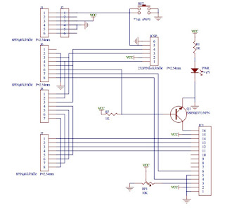
scheme skema LCD Shield for Arduino for complete reference, visit this web : http://www.hobbytronics.co.uk/arduino/arduino-shields

scheme skema keypad shield for arduino

Gambar
scheme skema keypad shield for arduino coding example : // include the library code: #include // initialize the library with the numbers of the interface pins LiquidCrystal lcd(8, 9, 4, 5, 6, 7); void setup() { // set up the LCD's number of columns and rows: lcd.begin(16, 2); // Print a message to the LCD. lcd.setCursor(0,0); lcd.print("LCD Key Shield"); lcd.setCursor(0,1); lcd.print("Press Key:"); } void loop() { int x; x = analogRead (0); lcd.setCursor(10,1); if (x < 60) { lcd.print ("Right "); } else if (x < 200) { lcd.print ("Up "); } else if (x < 400){ lcd.print ("Down "); } else if (x < 600){ lcd.print ("Left "); } else if (x < 800){ lcd.print ("Select"); } } daftar pustaka : http://osepp.com/products/shield-arduino-compatible/16x2-lcd-display-keypad-shield/

teks dari serial port ditampilkan di lcd dgn arduino

Gambar
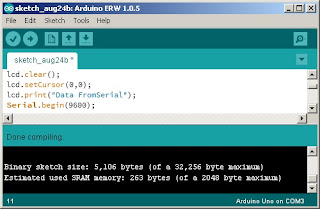
teks dari serial port (data teks dari komputer) untuk ditampilkan di lcd dgn arduino bisa kah? simak program ini : #include LiquidCrystal lcd(2,3,4,5,6,7); String textFromSerial =""; void setup() { lcd.begin(16,2); lcd.clear(); lcd.setCursor(0,0); lcd.print("Data FromSerial"); Serial.begin(9600); } void loop() { while(Serial.available()>0) { char data = Serial.read(); if(data == '\n') { lcd.setCursor(0,1); lcd.print(textFromSerial); textFromSerial=""; } else{ if(data!='\r') { textFromSerial += data; } } } } lalu sambung arduino dengan LCD nya ketik codingnya bila sukses akan tampil sepeti dibawah ini

Khazama AVR programmer

Khazama AVR programmer.. software mungil untuk mengupload file hex ke mikrokontroller http://khazama.com/project/programmer/

Arduino uno r3 Compatibel board

Arduino uno r3 compatibel board was designed for arduino modul. have same port_io pin figure.

atmega8 minsysboard

Gambar
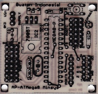
atmega8 minsysboard

sysminboard atmega16 mikro elektronika

Gambar
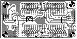
kita intip dulu desain minimum sistem board dari mikro elektronika.